

Carbon Fiber Manufacturing for Aerospace: A Complete Guide
Last Updated: November 13, 2026
Quick Summary
Carbon fiber manufacturing for aerospace produces CFRP parts with the highest strength-to-weight ratio of any production structural material, displacing aluminium and titanium in primary structures. Every kilogram removed from an airframe lowers fuel consumption and emissions on every flight for the aircraft's life, which is why higher unit production cost can still be the cheaper decision over a 20-year horizon.
- CFRP is strong along the fibre direction but comparatively weak across it, so design discipline matters more than with isotropic metals.
- Autoclave prepreg gives the lowest void content and highest mechanical properties but carries high capital cost and long cycles.
- Automated fiber placement wins on the hundredth part, not the first, because programming overhead is high.
- Prepreg out-time is logged against the material's qualified limit because tack and flow change as out-time accumulates.
- Carbon is cathodic relative to aluminium alloys, so direct joints in moisture accelerate corrosion of the metal.
Table of Contents
- Why Carbon Fiber Composites Dominate Aerospace Structures
- CFRP Fundamentals: Fiber, Resin Matrix and Laminate Design
- Aerospace Composite Manufacturing Processes Compared
- The Carbon Fiber Manufacturing Workflow From Prepreg to Part
- Material Selection Criteria for Aircraft Components
- CASA Regulations for Composite Aircraft Parts
- Carbon Fiber Structural Integrity Testing and Quality Assurance
- Repair, Maintenance and End-of-Life for Aerospace Composites
- Specifying Carbon Fiber Materials for Your Next Aerospace Build
- Frequently Asked Questions
Why Carbon Fiber Composites Dominate Aerospace Structures
Carbon fiber manufacturing for aerospace has become the default engineering answer to a simple problem: aircraft are judged on what they carry versus what they weigh. Carbon-fiber-reinforced polymer, or CFRP, delivers the highest strength-to-weight ratio of any production structural material available to airframers today. The shift to these materials is not hype. It is arithmetic.
Every kilogram removed from an airframe pays a dividend on every flight for the life of the aircraft. That is the throughline of this guide: weight is not a one-off saving, it is a recurring one, and that changes how you justify the manufacturing cost.
Strength-to-Weight Ratio Against Aluminium and Titanium
CFRP outperforms both aluminium and titanium alloys on specific strength and specific stiffness, which is why it has displaced them in primary structures. Aluminium alloys are cheap, well understood and easy to repair, but they fatigue. Titanium alloys resist heat and corrosion superbly, yet they are dense and expensive to machine. CFRP sits in a different bracket: a laminate can be tailored ply by ply so stiffness lands exactly where the load path needs it, with no surplus material carried as dead weight.
The trade-off is anisotropy. A composite is strong in the fibre direction and comparatively weak across it, so design discipline matters more than with isotropic metals.
Fuel Savings and Emissions Reduction in Service
Lower structural mass translates directly into lower fuel consumption and reduced emissions across the service life of the aircraft. The effect compounds: a lighter airframe needs less thrust, which allows smaller engines, which reduces fuel burn further. For operators, that is the business case. For manufacturers, it is the reason a higher unit production cost can still be the cheaper decision over a 20-year horizon.
CFRP Fundamentals: Fiber, Resin Matrix and Laminate Design
CFRP is a composite material in which high-strength carbon fibers carry structural load while a resin matrix binds them, transfers stress between plies and protects the fibers from moisture and impact. Neither component works alone. Fibers provide stiffness and tensile strength; the resin determines temperature tolerance, toughness and environmental durability.
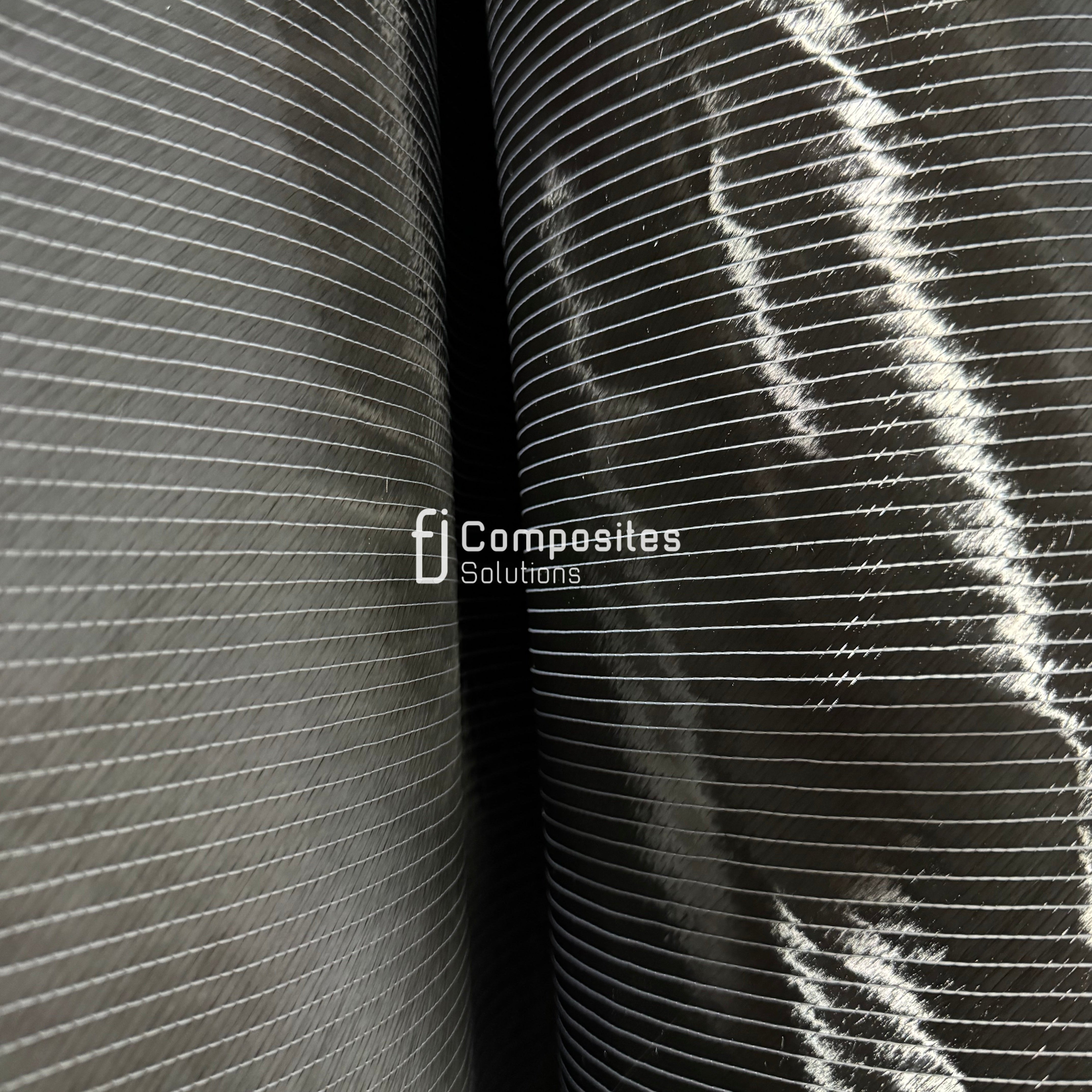
Laminate design is where aerospace engineering separates from general composites work. Each ply has an orientation, and stacking sequence governs how the part behaves under tension, compression, shear and torsion. A ±45° biaxial layup, for example, is chosen specifically for shear and torsional reinforcement, which is why it appears in wing skins and fuselage barrels. If you are working through laminate theory, it helps to see a real specification. Our 12K biaxial ±45° 300gsm carbon fibre fabric is listed with its tensile strength and modulus.
Aerospace Composite Manufacturing Processes Compared
Choosing a manufacturing process is the single biggest cost and capability decision in aerospace composite manufacturing, and there is no universally correct answer. The right process depends on part size, production volume, geometry complexity and the qualification burden you can carry.
Autoclave Prepreg Versus Resin Transfer Molding
Autoclave processing cures prepreg layups under elevated temperature and pressure. The cost is real: autoclaves are capital-intensive, cycle times are long, and part size is limited by vessel dimensions.
Resin transfer molding injects resin into a dry fiber preform inside a closed matched tool. It suits complex geometry and moderate volumes.
| Process | Best For | Strengths | Limitations |
|---|---|---|---|
| Autoclave prepreg | Primary structures, high performance | Lowest void content, highest mechanical properties | High capital cost, long cycles, size limited by vessel |
| Resin transfer molding | Complex geometry, moderate volume | Shorter cycles, good finish both faces, closed mould | Lower fiber volume fraction than autoclave |
| Automated fiber placement | Large aerostructures, repeatability | Fast deposition, precise orientation, low scrap | High equipment cost, programming intensive |
| Hand layup | Prototypes, low volume, repairs | Low tooling cost, flexible | Labor intensive, higher variability |
Automated Fiber Placement and Fiber Layup
Automated fiber placement deposits narrow prepreg tows at programmed orientations, building large structures with repeatable fiber alignment and minimal scrap. It has become the standard for fuselage barrels and wing skins where manual layup would be too slow or too variable. Hand layup still has a place: prototypes, one-off parts and repair work, where tooling cost would otherwise dominate.
The honest limitation of automation is programming overhead. For a single part, AFP is slower and dearer than a skilled laminator. It wins on the hundredth part, not the first.
The Carbon Fiber Manufacturing Workflow From Prepreg to Part
Every aerospace composite part follows the same spine: fiber selection, layup, consolidation, cure, machining and inspection. The differences between processes sit in how each step is executed, not in the sequence itself.
- Material receipt and storage. Prepreg arrives frozen and must be thawed in its sealed bag to prevent condensation forming on the resin. Out-time, the cumulative time a roll spends out of the freezer at room temperature, is logged against the material's qualified limit, because tack and flow change as out-time accumulates. A common pattern is to treat out-time as a formality until a batch starts showing inconsistent tack on the layup floor.
- Cutting and kitting. Ply shapes are cut by hand, by CNC cutter or by automated cutting table, then labelled by ply number and orientation and kitted in layup order. Mislabeling a ply orientation is one of the quietest defects in composites: the part looks correct and fails coupon testing later.
- Layup. Plies are placed on the tool at the specified orientation, with debulking cycles, typically vacuum debulks every few plies, to remove entrapped air and consolidate the stack. Debulk frequency is part of the qualified process specification, not a workshop preference.
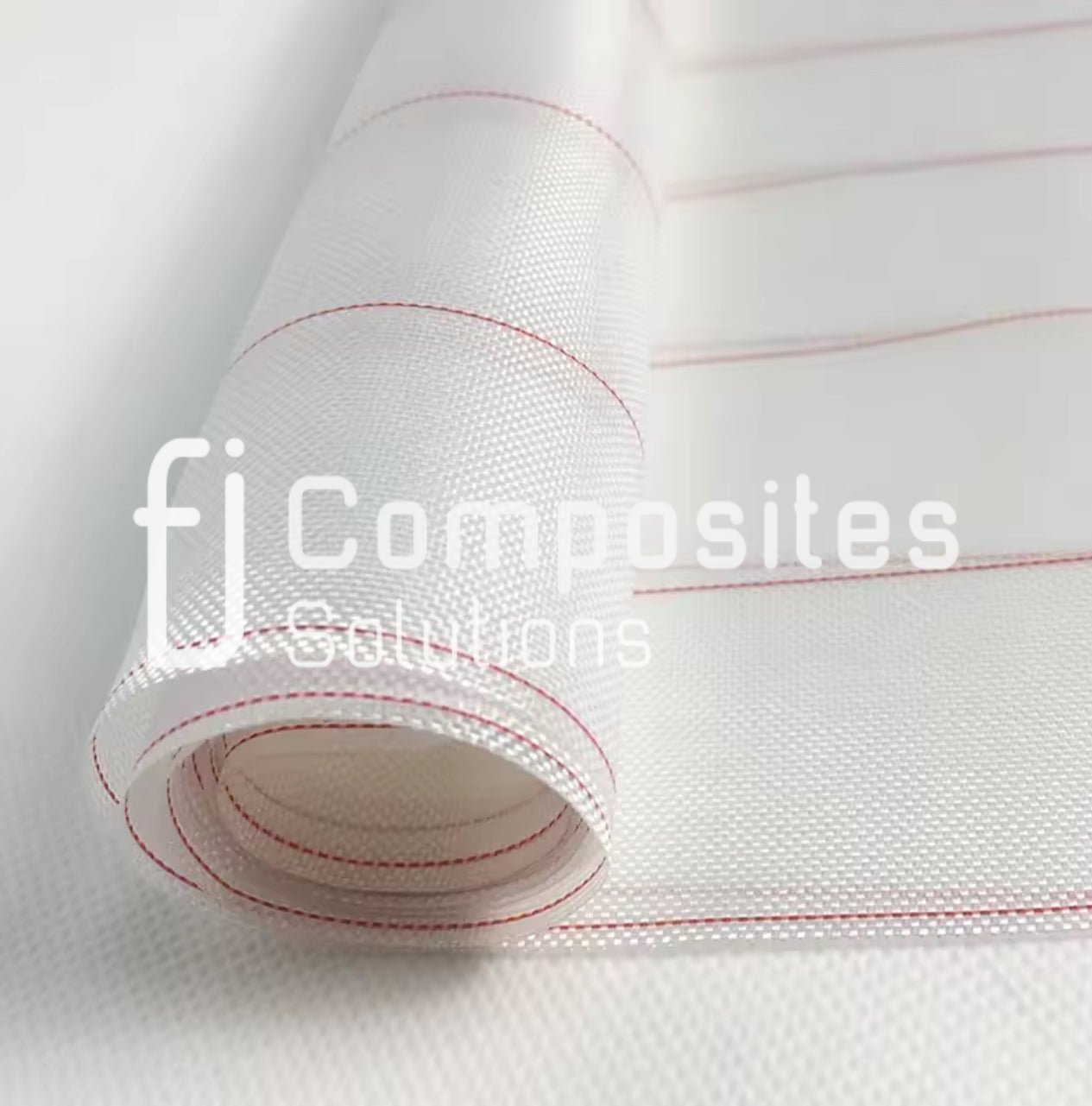
- Vacuum bagging. Consumables are applied in order: peel ply against the laminate, then release film, breather, and finally the bagging film sealed with sealant tape. The bag is leak-checked before cure. Watch out: a bag that passes a quick leak check at ambient can still fail under autoclave pressure and temperature, so the leak check should reflect the cure environment.
- Cure. The assembly is cured per the qualified cycle, a defined ramp rate, dwell temperature, pressure and cool-down, in an autoclave or oven depending on process. The cure cycle is part of the approved design, not a production variable to be optimised for throughput.
- Demould, trim and inspect. The part is demoulded, machined or trimmed to tolerance (often with diamond tooling to avoid delamination at the cut edge), and inspected before release. Dimensional inspection and non-destructive inspection are separate gates and both must pass.
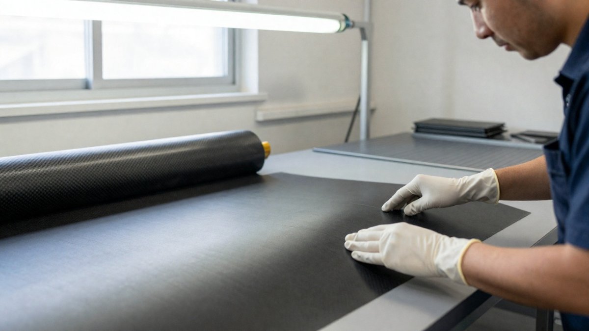
The consumables in step four are where inexperienced teams lose parts. Our professional grade peel ply for resin infusion and vacuum bagging and vacuum bagging sealant tape are the sort of items that quietly determine whether a cure produces a sound laminate or a scrap part.
Two workflow decisions deserve particular attention because they cascade through everything downstream. The first is tooling: invar, steel, aluminium and composite tools each have different thermal expansion behaviour, and a tool that expands differently from the laminate can induce residual stress or dimensional error in the cured part. The second is the process specification itself.
Material Selection Criteria for Aircraft Components
Material selection for aircraft components is a structured trade study, not a preference. We assess six criteria in order, and any candidate that fails a mandatory one is eliminated regardless of how well it scores elsewhere.
- Design allowables. Do you have qualified, statistically based strength values for this fiber-resin system?
- Service temperature. Does the resin matrix hold properties across the full operating envelope, including hot-day ground soak?
- Environmental durability. Will the laminate resist moisture uptake, UV and the fluids it will contact?
- Galvanic corrosion risk. Will the carbon fiber contact aluminium or steel fasteners, and is isolation specified?
- Damage tolerance. Does the structure tolerate the required impact without catastrophic propagation?
- Manufacturability and cost. Can the part be made repeatably at the required rate and price?
Galvanic corrosion deserves particular attention. Carbon is cathodic relative to aluminium alloys, so a direct joint in the presence of moisture accelerates corrosion of the metal. Isolation plies, sealants and compatible fasteners are not optional details.
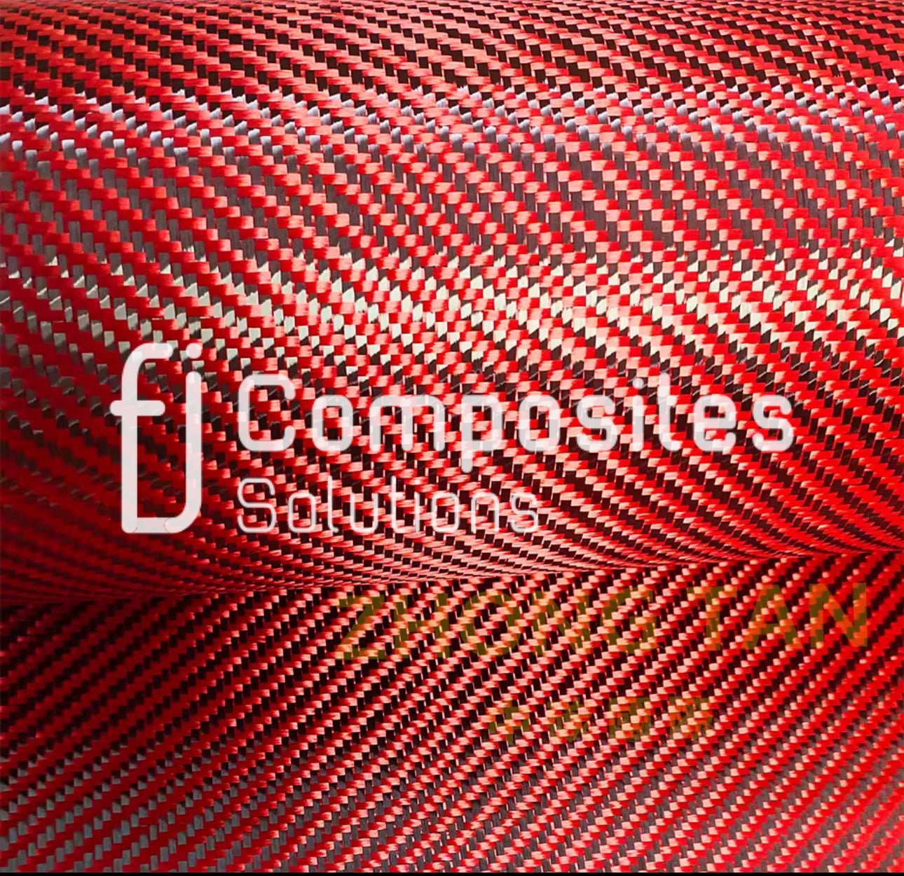
Where pure carbon lacks the toughness a component needs, hybrid reinforcement can be the better answer. Our Kevlar aramid carbon hybrid twill woven fabric is one option worth evaluating for parts that need impact resistance alongside stiffness.
CASA Regulations for Composite Aircraft Parts
Composite aircraft parts in Australia are subject to the Civil Aviation Safety Regulations, administered by the Civil Aviation Safety Authority, and readers should consult CASA directly for current requirements.
The practical implication for manufacturers is that your process is part of the approved design. A qualified laminate made outside its qualified process specification is not a qualified part. That means cure cycles, material storage, layup records and inspection methods all need documented control.
We recommend working from the CASA regulations and advisory material directly rather than second-hand summaries, because acceptable means of compliance change and the obligation sits with the approval holder.
Carbon Fiber Structural Integrity Testing and Quality Assurance
Carbon fiber structural integrity testing typically combines non-destructive inspection with destructive coupon testing. Both are commonly used. NDI catches the part that went wrong today; coupon testing proves the process will not go wrong tomorrow.
The defect types that matter most in aerospace laminates are consistent across processes, even if their causes differ:
- Porosity and voids. Entrapped air or volatiles that were not removed during consolidation. Void content above the qualified limit reduces interlaminar shear strength and is usually a bagging, debulk or cure-pressure problem rather than a material problem.
- Delamination. Separation between plies, often from impact, machining, or insufficient consolidation. It is the defect ultrasonic inspection is best at finding.
- Fiber waviness. Out-of-plane crimping of fibers, which can come from layup over tight radii or from uneven tool pressure, and which degrades compressive strength disproportionately.
- Foreign objects and inclusions. Backing film, glove fragments or release agent trapped between plies, a defect that is easy to prevent with housekeeping discipline and expensive to find after cure.
Non-destructive methods used in aerospace composite fabrication include ultrasonic inspection (pulse-echo and through-transmission) for delamination and porosity, tap testing for disbonds, and thermography for near-surface defects. Each has a detection limit: ultrasonic inspection struggles with certain geometries and thick sections, tap testing depends heavily on operator skill, and thermography is best suited to near-surface flaws.
Destructive programmes cover fiber volume fraction, void content, glass transition temperature and short-beam shear on process control coupons. The coupon programme is not a one-off qualification exercise: process control coupons are typically run alongside production to demonstrate the process has not drifted, and the results are retained as part of the quality record.
A common mistake is treating NDI as a final gate only. In practice, in-process checks during layup and debulking catch far more defects at far lower cost than scrapping a cured part.
Repair, Maintenance and End-of-Life for Aerospace Composites
Repair of aerospace composites is a bonded or bolted restoration that returns the structure to its design allowables, and it is a discipline in its own right. Scarf repairs, stepped lap repairs and bonded patch repairs each have defined limits on damage size and location. Beyond those limits, the part is replaced.
Maintenance programmes need to account for damage modes that metals do not exhibit: barely visible impact damage, delamination that propagates under load, and moisture ingress into the laminate. Inspection intervals should reflect those modes rather than being inherited from a metal baseline.
End-of-life is the least mature part of the lifecycle. Thermoset composites are difficult to recycle into structural applications, and most current pathways downcycle into fillers or cement kiln fuel. Design for disassembly and thermoplastic matrices are the areas to watch.
Specifying Carbon Fiber Materials for Your Next Aerospace Build
Specifying materials well is mostly about writing down what you actually need before you talk to a supplier. Vague briefs produce expensive mistakes.
Start with the load case and the process. A hand-laid prototype and an autoclave-qualified primary structure need different fabrics, different tack levels and different documentation. Then specify fiber type and tow size, areal weight, weave or orientation, width, resin compatibility and the traceability you require.
If you are comparing what is available before you commit, you can browse our carbon fibre manufacturing range. For teams building UAV airframes rather than manned structures, the design logic is the same. Our custom composite production covers UAV platforms from 1.2m to 6.1m wingspan.
The hardest part of aerospace composites is not choosing a fiber. It is holding process discipline across every ply, every cure and every inspection record, because that is what turns a good laminate into a qualified part.
Frequently Asked Questions
What are the primary benefits of using carbon fiber in aerospace manufacturing?
The main benefit is weight. Carbon fiber composites deliver a high strength-to-weight ratio, so structural components can be lighter than equivalent aluminium or titanium assemblies. Lower airframe weight cuts fuel consumption and emissions over the aircraft's life. Composites also resist fatigue cracking and can be formed into complex aerodynamic shapes with fewer fasteners. The trade-offs are higher raw material cost, more involved manufacturing, and inspection methods that differ from metal airframes.
How does the carbon fiber manufacturing process ensure structural integrity for aircraft?
Integrity comes from control at every stage. Fiber layup orientation, prepreg storage, cure temperature and pressure, and void content are all specified and recorded. Coupon and element testing follows the laminate through to full-scale static and fatigue tests. Non-destructive inspection such as ultrasonic C-scan then checks production parts for delamination and porosity. Traceability of resin matrix, fabric batch and cure cycle lets engineers tie each part back to its process record.
What Australian standards govern the use of composite materials in aviation?
The Civil Aviation Safety Authority (CASA) regulates aviation in Australia, and composite parts for aircraft need to meet the applicable airworthiness standards accepted by CASA, typically via a type certificate, supplemental type certificate or approved modification. Manufacturers work to documented process specifications and quality systems, with material and test evidence submitted for approval. For experimental or remotely piloted platforms the pathway differs, so confirm the category with CASA before committing to a production method.
What are the challenges of repairing carbon fiber aerospace components?
Composite repair is more involved than patching metal. Damage often hides below the surface as delamination or matrix cracking, so inspection comes first. A bonded or bolted scarf repair must restore load paths, which means matching the original fiber orientation and laminate schedule, then curing under controlled temperature and pressure. Galvanic corrosion is a real risk where carbon fiber meets aluminium fasteners, so material compatibility and isolation matter. Repairs also need their own approval and test evidence.
How do carbon fiber composites improve fuel efficiency in modern aircraft?
Every kilogram removed from an airframe reduces the lift and thrust needed, which lowers fuel burn across the whole service life. Composite structures also allow smoother aerodynamic surfaces and fewer joints, trimming drag. The weight reduction compounds: lighter structure permits smaller engines or more payload for the same fuel.
Which carbon fiber fabric should I start with for an aerospace or UAV component?
It depends on the load case. A biaxial ±45° fabric such as the 12K Biaxial Carbon Fibre Fabric 250gsm, listed at $59.95 per linear metre, is one option for shear and torsional reinforcement. A unidirectional fabric such as the 200gsm 12K UD at $39.95 per linear metre is another. Confirm resin compatibility and run a test laminate before production.
