

How to Integrate LiDAR Sensors on Carbon Drones
Last Updated: November 14, 2026
Quick Summary
To integrate lidar sensors on carbon drones, mount the scanner under the belly near the centre of gravity with a bracket that spreads load into spars or a reinforced panel, then give the payload its own fused circuit, a single-point ground and PPS time sync. Finish with vibration isolation, boresight calibration and a ground resonance test before flight.
- Bond a 3K carbon plate to the skin so the bracket spreads load over a wider area.
- Plan around 80% depth of discharge and divide usable capacity by total aircraft current draw.
- Bond the payload ground at a single point and keep return current off the airframe structure.
- Run a ground vibration test with props fitted and shift resonance away from cruise RPM.
- Do boresight calibration only after the payload is finally mounted, since any mount change invalidates it.
Table of Contents
- Why Carbon Frames Suit LiDAR Payloads
- Drone LiDAR Payload Mounting on a Carbon Airframe
- Drone Payload Power Requirements and Electrical Integration
- LiDAR Drone Vibration Isolation and Resonance Testing
- LiDAR Sensor Calibration for Drones
- Flight Planning, Point Density and Data Quality
- Safety, Airworthiness and Troubleshooting After Modification
- Planning Your LiDAR Integration Build
- Frequently Asked Questions
Why Carbon Frames Suit LiDAR Payloads
Carbon-fibre airframes and LiDAR payloads are a natural match. A carbon drone frame gives you stiffness without mass: less flex means less misalignment between sensor and airframe, and less mass means more endurance for long survey lines.
The frame is not just a carrier, it is part of the measurement system.
Here is why carbon suits LiDAR sensors so well:
- High stiffness-to-weight ratio. Carbon plates and tubes resist bending under payload load.
- Low thermal expansion. The frame moves less as temperatures shift between ground and altitude.
- Good fatigue resistance. Repeated flights do not loosen the structure the way some metals can.
- Machinable. You can cut and drill mounting points with the right composite tooling.
That last point is where most builds succeed or fail. A carbon airframe gives you a clean, rigid platform, but you still have to mount the payload correctly, power it properly, and isolate it from vibration.
Drone LiDAR Payload Mounting on a Carbon Airframe
Drone LiDAR payload mounting on a carbon airframe is a structural design problem before it is a bracket problem.
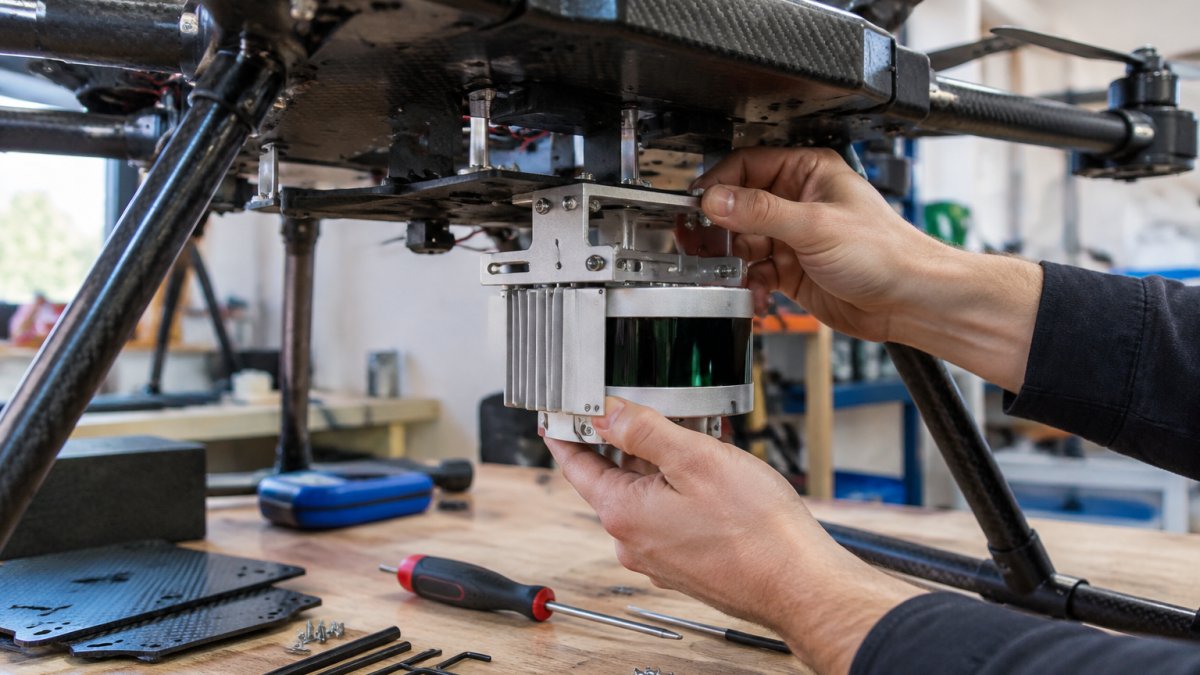
Start with the load path. The scanner's mass plus dynamic flight loads must travel from the bracket into primary structure, spars, booms, or a reinforced belly panel, not into thin unsupported skin.
Before you drill anything, check these points:
- Confirm the scanner's mounting hole pattern against your bracket drawing.
- Check that the bracket spreads load across a wide area of skin, not one small patch.
- Keep the sensor axis parallel to the airframe's reference axis.
- Leave clearance for cabling and connector access.
- Identify the nearest spar, rib or boom and tie the bracket into it where possible.
A common mistake is bolting straight through a thin carbon skin with no backing, which concentrates stress at the holes and can crack the laminate. Use a backing plate or bonded insert instead.
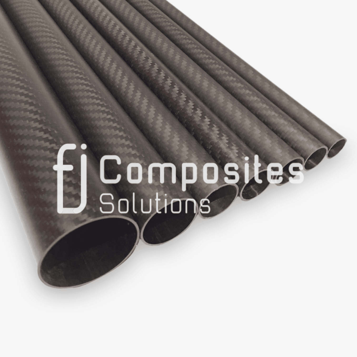
If you need structural tubing for standoffs or a mounting frame, our 3K twill carbon fibre tubes run to 1000 mm and cut cleanly for fabrication. For a full range of diameters and wall thicknesses, browse the carbon fibre tubes before you finalise your bracket design.
How Carbon Laminate Carries Payload Load
Carbon-fibre plate is anisotropic: strong along the fibres, comparatively weak across them and through the thickness. A bolt tightened through bare laminate crushes the matrix around the hole and can delaminate the plies, so spread bearing load over a larger area.
Three practical approaches work on small airframes:
- Backing plate. Bond or bolt a plate of the same or thicker laminate on the opposite face so the bolt clamps a sandwich rather than a single skin, doubling bearing area and reducing crush.
- Bonded insert. Pot a metal or composite insert into a locally thickened zone so the fastener bears on the insert, not the skin, the better choice where you remove the payload repeatedly.
- Through-bolted hardpoint tied to structure. Where a spar or boom sits behind the skin, pass the fastener through both so load bypasses the skin entirely.
Whichever you choose, keep fastener holes slightly oversized and use large-area washers on both faces. Tighten to the manufacturer's torque rather than by feel; over-torquing crushes laminate, under-torquing lets the joint fret.
Reinforcing the Mounting Zone
Bond a plate of 3K carbon fibre sheet to the underside of the skin where the bracket sits, spreading load across a larger area and stiffening the local panel. Our 3K carbon fibre plates and sheets come in a diagonal twill pattern and are available in thicknesses from approximately 0.5 mm to 10 mm, depending on requirement.

Two rules we would give any builder:
- Match the reinforcement thickness to the bracket footprint, not to the whole airframe.
- Bond the plate with a proper structural adhesive and clamp it flat while it cures.
Watch out: reinforcing only the bolt holes and not the surrounding panel is the most common cause of skin cracking around a payload mount, because the stiffened holes attract load the unreinforced panel cannot spread.
Preserving Frame Stiffness
A carbon frame's stiffness comes from continuous fibre paths through spars, booms and skins. Cutting a large access hole, removing a shear web, or interrupting a boom to fit a mount can drop stiffness sharply and change vibration behaviour.
Keep cutouts small and round-cornered rather than square, because sharp corners concentrate stress. If you must interrupt a load path, add a local doubler or bolted splice to carry load around the opening.
Centre of Gravity and Sensor Placement
Place the scanner as close to the airframe's existing centre of gravity as the field of view allows, then check balance before the first flight. If the payload shifts the balance point, move the battery pack to compensate rather than adding dead weight.
Also keep the sensor clear of heat sources and exhaust paths; a hot scanner drifts, and drift shows up as error in your point cloud.
Drone Payload Power Requirements and Electrical Integration
Drone payload power requirements usually decide the whole electrical design. A LiDAR scanner draws steady current for the laser and the spinning head, and that load competes with the airframe's own systems for battery capacity.
Add up the payload's current draw at its rated voltage, then compare that against your flight battery's usable capacity. If the payload eats a large share of the budget, your flight time drops accordingly.
- Size the payload battery or power tap for continuous draw, not peak draw.
- Add a separate BMS or protection board for a dedicated payload pack.
- Keep payload wiring on its own circuit, away from flight-critical power.
- Fuse the payload circuit independently.
- Check that the payload's input voltage tolerance covers the full battery range, not just nominal.
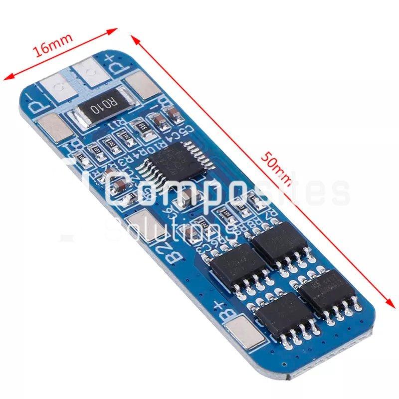
For a dedicated payload pack, our 3S 10A 12V lithium battery charger protection board gives you a BMS to manage charging and discharge safely. Pair it with Samsung INR18650 30Q cells if you are building the pack yourself.
Voltage, Current and Grounding Checks
Before first power-up, verify the payload's supply against its datasheet: minimum and maximum input voltage, steady current, peak current at spin-up, and inrush at switch-on.
Grounding deserves its own check. Bond the payload's ground to the airframe's common ground at a single point to avoid ground loops, which show up as noise on data lines and can corrupt timing signals.
Wiring, Shielding and Connector Choices
Route payload power and signal cables separately. Keep signal runs short and twisted where you can.
Choose keyed, locking connectors rated for the vibration environment rather than push-fit headers that work loose in flight.
Watch out: running payload power and the GNSS antenna cable in the same bundle is a frequent cause of intermittent satellite dropouts, because the switching noise on the power conductor couples into the sensitive antenna feed.
Time Synchronisation
Time synchronisation matters more than most builders expect. The scanner, GNSS receiver and IMU all need a shared time base; without it, georeferencing drifts and your point cloud smears.
Check synchronisation on the bench before flight: log a known event on both the scanner and the flight controller and compare timestamps. A consistent offset can be corrected in software; a drifting offset points to a wiring or configuration fault that will ruin the survey.
LiDAR Drone Vibration Isolation and Resonance Testing
LiDAR drone vibration isolation protects both the data and the hardware. Props, motors and airframe resonance all feed vibration into the sensor, and a laser scanner does not like it.
Mount the scanner on a compliant interface, not directly to rigid structure. Rubber isolators, silicone grommets or a damped plate all work.
Then test it. Here is the sequence we would follow:
- Fit the payload and check the mount is tight.
- Run a ground vibration test with props fitted and motors spinning at low throttle.
- Watch for resonance points where the airframe shakes harder at one specific RPM.
- Adjust isolator stiffness or add mass to shift resonance away from your cruise RPM.
- Repeat at hover and cruise throttle settings.
A common mistake is skipping the ground test and going straight to flight. Ground testing is cheap and catches most problems.
LiDAR Sensor Calibration for Drones
LiDAR sensor calibration for drones has two parts: boresight calibration and range calibration. Boresight sets the sensor's alignment relative to the IMU and GNSS. Range calibration checks the scanner's distance accuracy.
Do boresight calibration after the payload is finally mounted. Any change to the mount invalidates it.
The practical steps:
- Fly a calibration pattern over a known target area with good geometry.
- Collect overlapping passes in different directions.
- Process the data and check for misalignment between passes.
- Adjust the boresight angles and reprocess.
- Repeat until passes align within your accuracy target.
Check the scanner's range accuracy against a known baseline before you trust the data. A scanner that reads short or long will bias every point cloud it produces.
Flight Planning, Point Density and Data Quality
Flight planning sets your point density, and point density sets what you can actually see in the data. Fly too high and vegetation and small features disappear. Fly too low and you burn flight time for coverage you did not need.
Plan around these settings:
- Altitude: lower altitude means higher point density but narrower swath.
- Speed: slower speed means more pulses per metre of ground.
- Overlap: overlapping passes fill shadow gaps behind terrain and structures.
- Ground control: place targets so the survey can be tied to known coordinates.
Check your point cloud for gaps after the first flight. Shadowed areas behind ridges, buildings and dense canopy are normal, but unexpected gaps usually mean a planning error or a sensor issue.
Safety, Airworthiness and Troubleshooting After Modification
Any modification to an airframe changes its airworthiness. Adding a payload shifts mass, changes vibration behaviour and alters power draw, and each of those affects how the aircraft behaves in the air.
Before you fly a modified airframe, work through this checklist:
- Payload mount inspected and fasteners torqued
- Centre of gravity rechecked with payload fitted
- Payload circuit fused and independently switched
- Vibration ground test completed
- Boresight calibration done after final mounting
- Flight battery capacity checked against new draw
- Fail-safe and return-to-home tested with payload fitted
- Local operating rules and airspace requirements confirmed
Watch out: flying a modified airframe without rechecking the centre of gravity can make the aircraft unstable in flight.
Troubleshooting follows a similar pattern. If the point cloud looks smeared, suspect time synchronisation first. If it looks noisy, suspect vibration. If passes do not align, suspect boresight.
Planning Your LiDAR Integration Build
A LiDAR integration build succeeds when the mechanical, electrical and data sides are planned together. Most failures we see come from treating them as separate jobs.
Here is the order we would work in:
| Stage | What to Do | Key Check |
|---|---|---|
| Mechanical | Design bracket, reinforce mount zone, fit payload | Mount is rigid and load is spread |
| Balance | Check centre of gravity with payload fitted | Balance point within limits |
| Electrical | Size payload power, add BMS, route and shield wiring | Clean power, independent circuit |
| Timing | Set up PPS and time sync between scanner, GNSS and IMU | Timestamps align |
| Vibration | Ground test, find resonance, tune isolators | No resonance at cruise RPM |
| Calibration | Boresight and range calibration after final mount | Passes align within target |
| Flight Test | Plan flight, collect data, check point cloud | Density and coverage meet spec |
If you are building a custom airframe rather than modifying an existing one, a purpose-built composite platform saves you most of this work.
Integrating LiDAR sensors on a carbon drone is a mechanical, electrical and data problem at the same time.
Frequently Asked Questions
Can carbon fibre interfere with a drone's LiDAR sensor?
Carbon fibre itself does not block the laser returns a LiDAR sensor relies on, because the sensor measures distance to the ground and objects below the aircraft, not through the frame. The real risks are electrical: carbon is conductive, so it can create ground loops or shield radio and GNSS signals if cabling is routed carelessly. Keep GNSS antennas on a mast clear of the frame, bond the airframe to a single ground reference, and route sensor cables away from carbon edges that could chafe insulation.
How do you reduce vibration in a drone LiDAR payload?
Start with a stiff mounting plate rather than a flexible one, then add elastomer isolators rated for the payload mass so the mount does not bottom out. Balance propellers and check motor mounts before adding more damping, since imbalance is usually the source. Run a hover test and log IMU data to find resonance peaks, then adjust isolator stiffness or add mass to shift the natural frequency away from rotor RPM. Confirm the result with a short flight and a point cloud check for smeared or doubled surfaces.
How do you power a LiDAR sensor from a drone?
Calculate the sensor's continuous draw plus peaks, then confirm your battery and power distribution board can supply it without pulling voltage below the sensor's minimum. Most survey LiDAR units run on a regulated supply, so use a dedicated BEC rated above the measured peak rather than tapping a flight-controller rail. Budget the extra current into flight time: a payload drawing 15 W from a 6S pack costs roughly 0.7 A, which shortens endurance noticeably on long-range missions. Fuse the payload circuit separately.
What flight tests should you perform after integrating a LiDAR payload?
Fly a short hover and slow circuit first to check vibration logs, current draw and GNSS satellite count with the payload running. Then fly a calibration pattern over a known surface to verify boresight alignment and time synchronisation. Finally, survey a small area with ground control points and compare the resulting point cloud against measured coordinates. Only scale to full mission profiles once accuracy, endurance and thermal behaviour are confirmed across two or three flights.
